1、启动STAR-CCM+,新建simulation,选择Parallel on Local Host,Compute Processes设为2,点击OK,保存模型为radiator_hx.sim。
2、点击Import Surface Mesh,导入radiator_parts.x_b。参数默认,勾选Open Geometry Scene After Import。
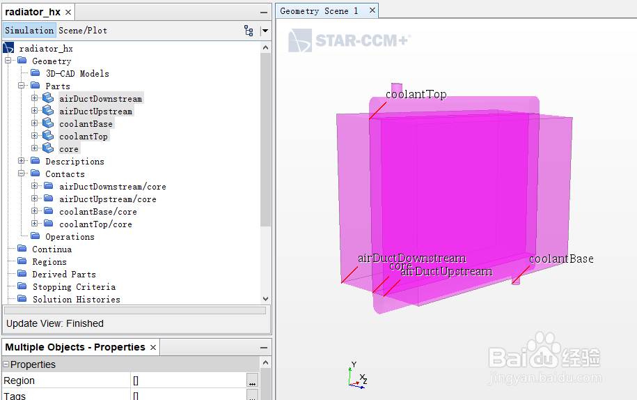
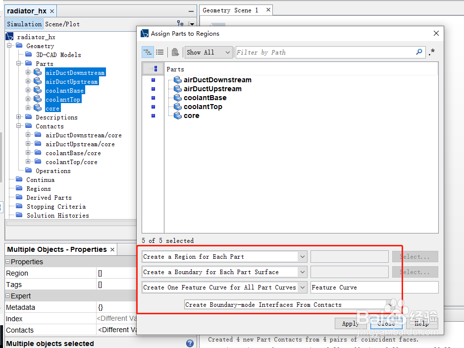
1、同时选中所有Part,右键选择Assign Parts to Regions,相关设置如图。
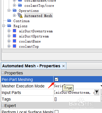
2、点击Operations > New > Mesh > Automated Mesh,选择所有Part,Enabled Meshers选择Surface Remesher、Trimmed Cell Mesher,勾选Per-Part Meshing。

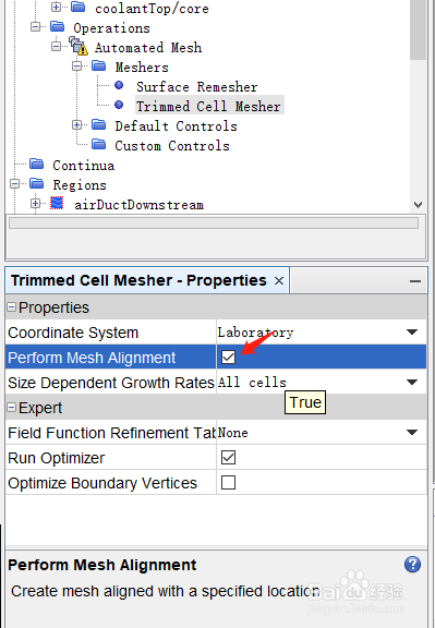
3、点击Automated Mesh > Meshers > Trimmed Cell Mesher,勾选Perform Mesh Alignment。
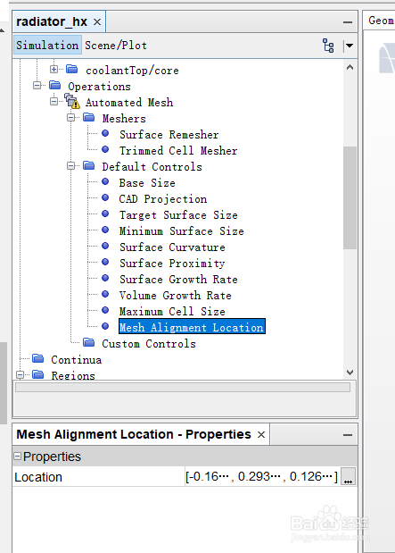
4、点击Automated Mesh > Default Controls,Base Size设为25.6 mm,Minimum Surface Size > Percentage of Base设为1,Mesh Alignment Location设为[-0.166693,0.293814,0.126133],其他默认。
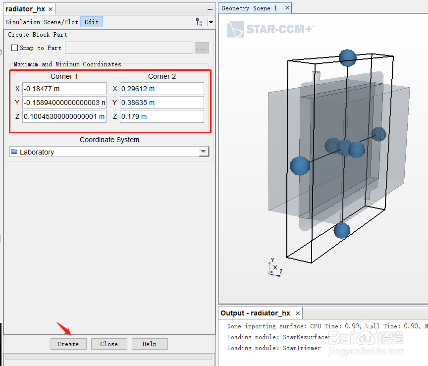
5、点击Geometry > Parts,右键New Shape Part > Block。Corner 1为[-0.18477,-0.15894,0.100453],Corner 2为[0.29612, 0.38635, 0.179],点击Create。
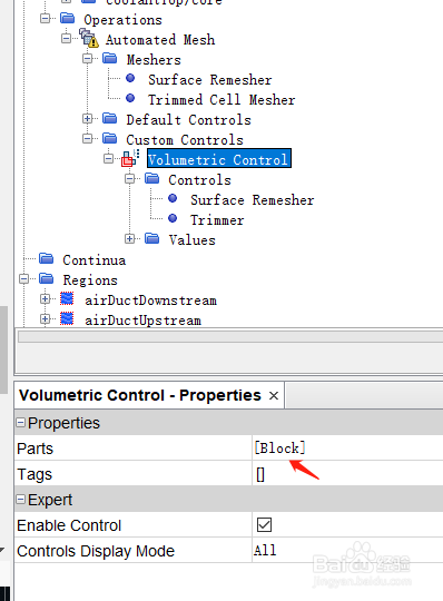
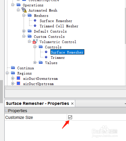
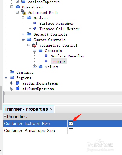
6、点击Operations > Automated Mesh > Custom Controls,右键New > Volumetri Control。Parts选择Block,勾选Surface Remesher > Customize Size,Trimmer > Customize Isotropic Size。
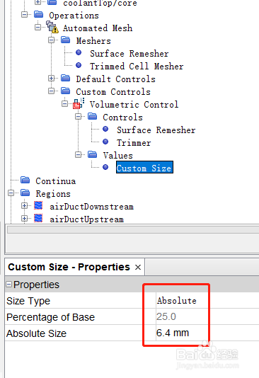
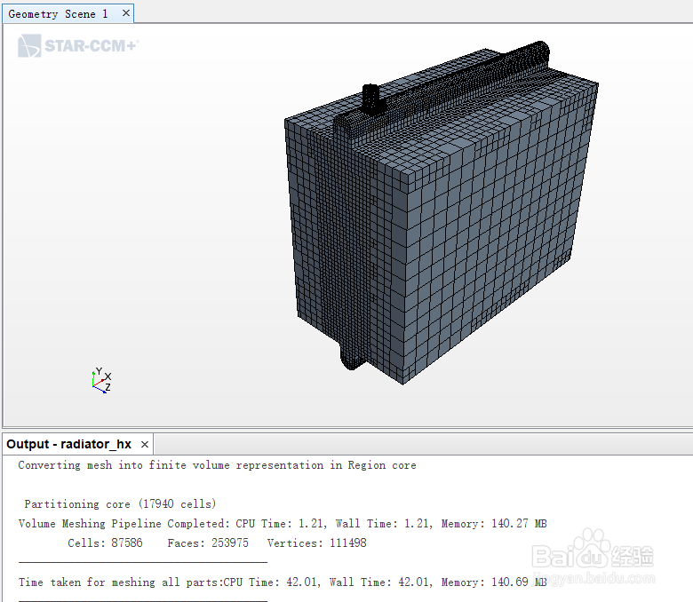
7、Custom Size设为6.4 mm。右键Automated Mesh,点击Execute,生成网格。
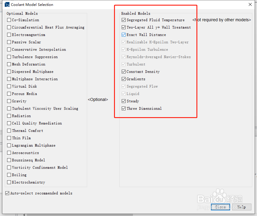
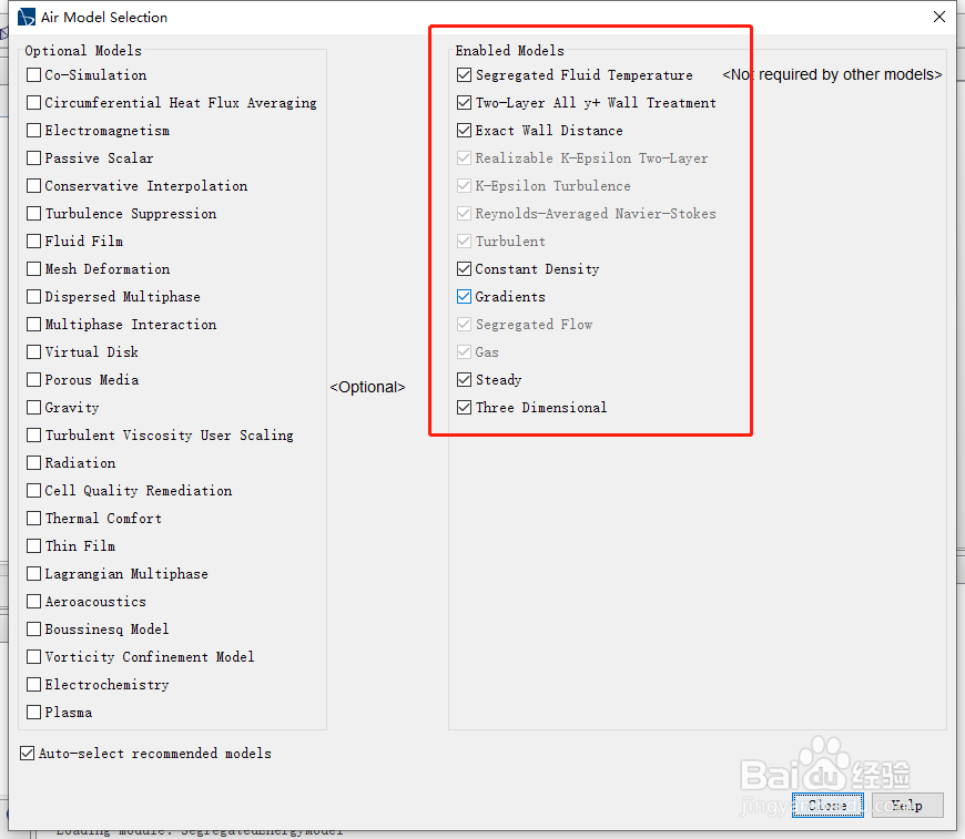
1、点击Continua > New > Physics Continuum,分别创建流体和固体模型,并重命名为Air和Coolant。
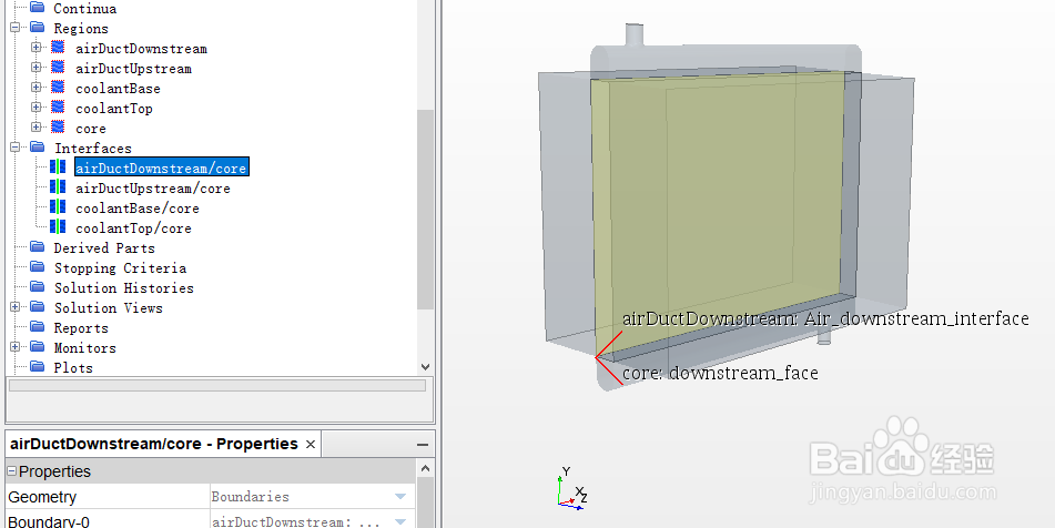
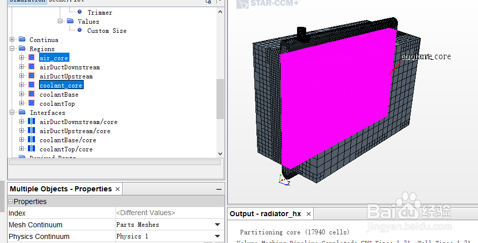
1、右键Regions > core,重命名为air_core,复制air_core再命名为coolant_core。
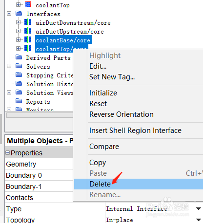
2、删除两个Interface:coolantBase/core,coolantTop/core。
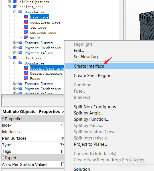
创建两个Interface:
同时选中coolant core > Boundaries > base_face和coolantBase > Boundaries > Coolant_base_interface,右键点击Create Interface。
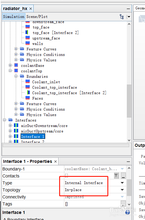
同理,同时选中coolant core > Boundaries > top_face和coolantTop > Boundaries > Coolant_top_interface创建Interface。
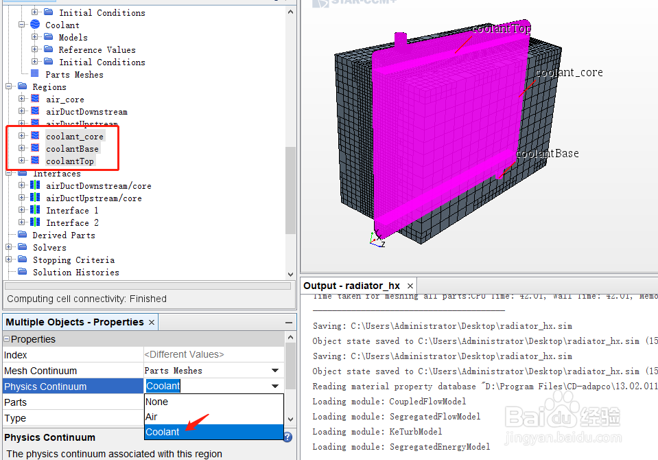
3、在Region栏,coolant_core,coolantBase,coolantTop对应的Physics Continuum选择Coolant;air_core,airDuctDownstream,airDuctUpstream选择Air。
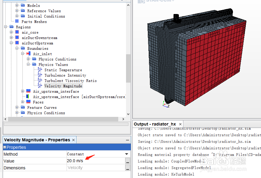
4、点击Regions > airDuctUpstream > Boundaries > Air_inlet,Type类型选择Velocity Inlet,Physics Values 栏,Static Temperature设为308 K,20 m/s。
同理,点击Regions > airDuctDownstream > Boundaries > Air_pressure_out,Type类型选择Pressure Outlet。
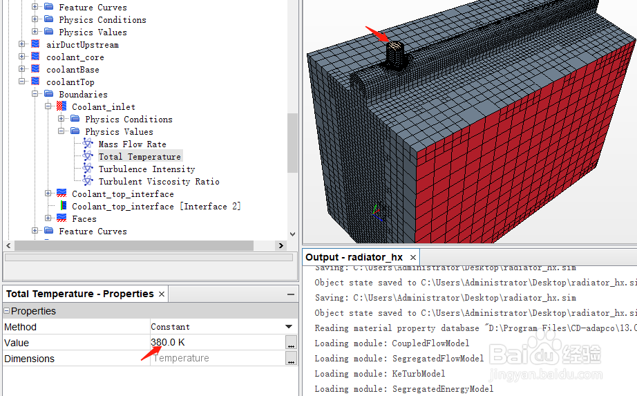
5、点击Regions > coolantTop > Boundaries > Coolant_inlet,Type类型选择Mass Flow Inlet,Physics Values 栏,Mass Flow Rate设为1.8 kg/s,Total Temperature设为380 K。
同理,点击Regions > coolantBase > Boundaries > Coolant_pressure_out,Type类型选择Pressur Outlet。
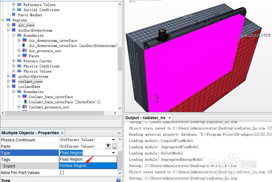
6、将air_core和coolant_core简化为多孔介质模型,在Region栏,air_core和coolant_core的Type选择Porous Region。
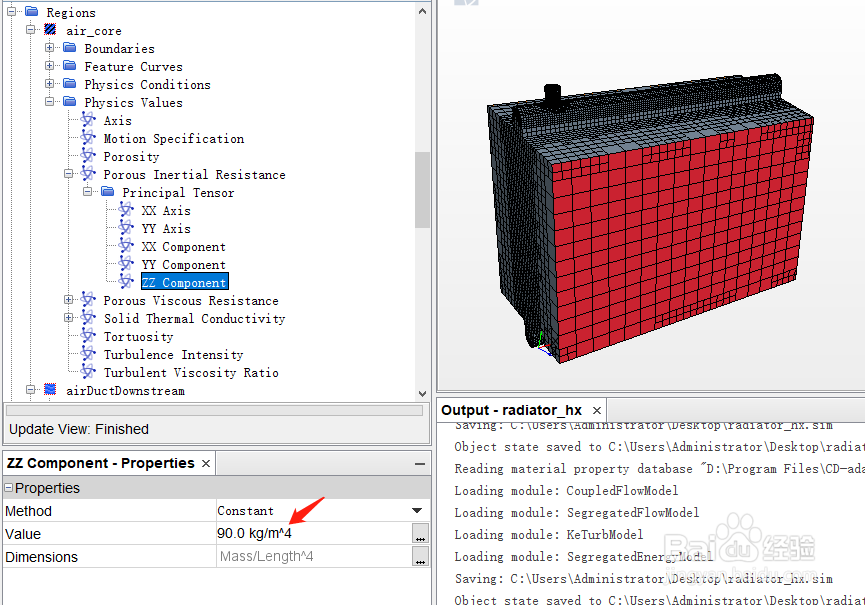
7、点击air_core > Physics Values > Porous Inertial Resistance,分别设置XX/YY/ZZ Component值为1e4,1e4,90 kg/m4;Porous Viscous Resistance,分别设置XX/YY/ZZ Component值为1e5,1e5,450 kg/m3-s。
同理,coolant_core > Physics Values > Porous Inertial Resistance ,分别设置XX/YY/ZZ Component值为1e8,2e6,1e8 kg/m4;Porous Viscous Resistance,分别设置XX/YY/ZZ Component值为1e6,5.5e4,1e6 kg/m3-s。
惯性阻力和粘性阻力系数本例采用软件自带help中的数据,在具体案例中应根据实验或仿真进行标定得到。
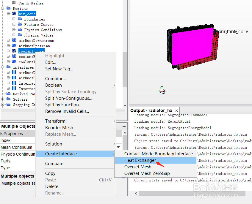
1、在Region栏同时选中air_core和coolant_core,右键Create Interface > Heat Exchanger。
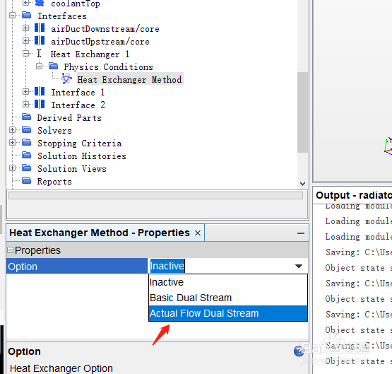
2、点击Interfaces > Heat Exchanger 1 > Physics Conditions > Heat Exchanger Method,Option选择Actual Flow Dual Stream。
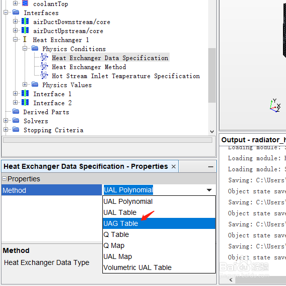
3、点击Heat Exchanger Data Specification,Method选择UAG Table。
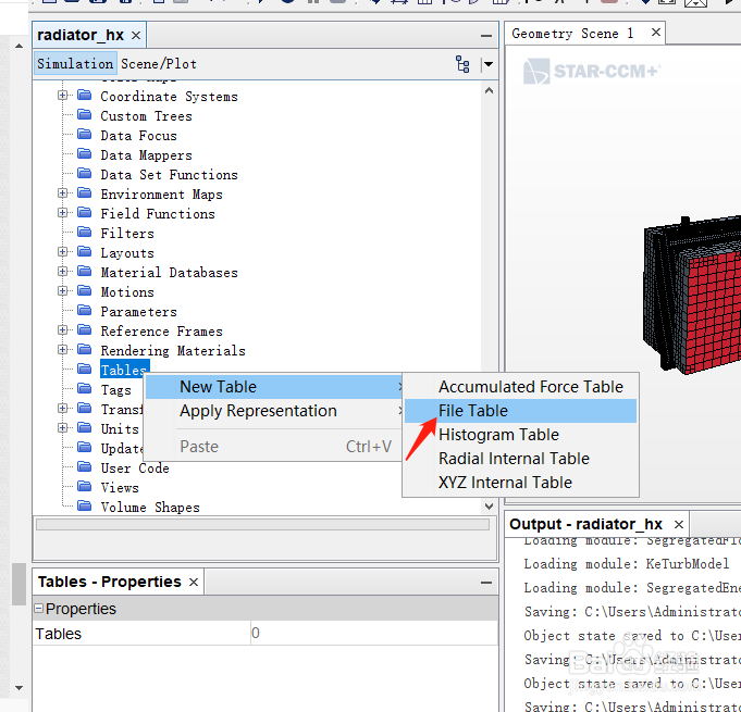
4、点击Tools > Table,右键New Table > File Table,导入uag_table.csv。
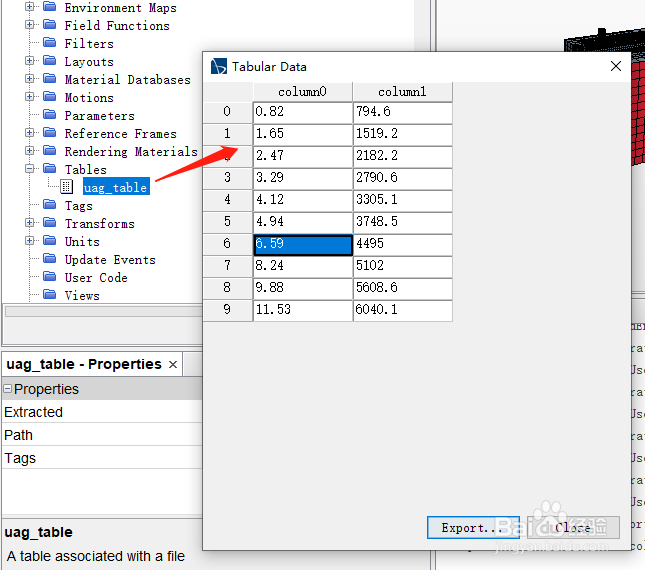
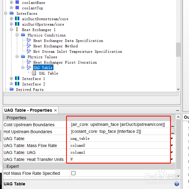
5、点击Interfaces > Heat Exchanger 1 > Physics Values > UAG Table,Table选择uag_table,Mass Flow Rate选择column0,UAG选择column1,Cold Upstream Boundaries选择upstream_face [airDuctUpstream/core],Hot Upstream Boundaries选择top_face [Interface 2]。
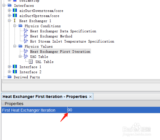
6、点击Physics Values > Heat Exchanger First Iteration,设为90。
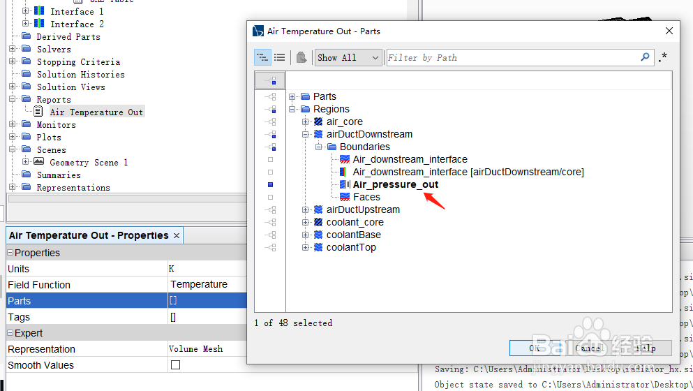
1、监控空气出口温度。右键Reports选择New Report > Surface Average,重命名为Air Temperature Out,Parts选择Regions > airDuctDownstream > Air_pressure_out,Field Function选择Temperature。
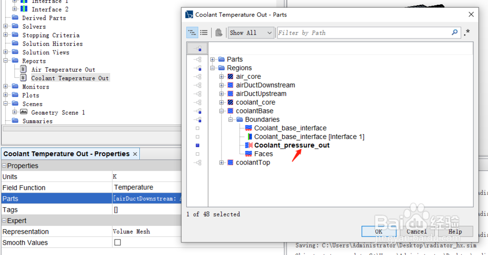
2、监控冷却液出口温度。复制Reports> Air Temperature Out,重命名为Coolant Temperature Out,Parts选择Regions > coolantBase > Coolant_pressure_out。
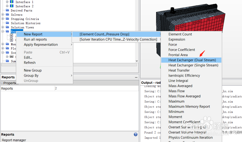
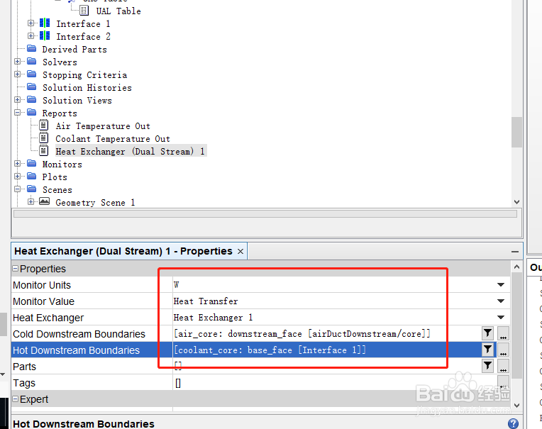
3、监测两种介质的热交换量。右键Reports选择New Report > Heat Exchanger (Dual Stream),选择Heat Exchanger 1,Cold Downstream Boundaries选择downstream_face [airDuctDownstream/core],Hot Downstream Boundaries选择base_face [Interface 1]。
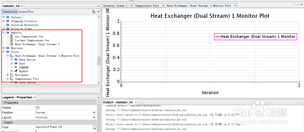
4、创建Plot。同时选中Air Temperature Out和Coolant Temperature Out,右键Create Monitor and Plot from Report,选择Single Plot,重命名为Temperature Plot 。同理,创建Heat Exchanger (Dual Stream) 1报告。
5、创建监控截面。
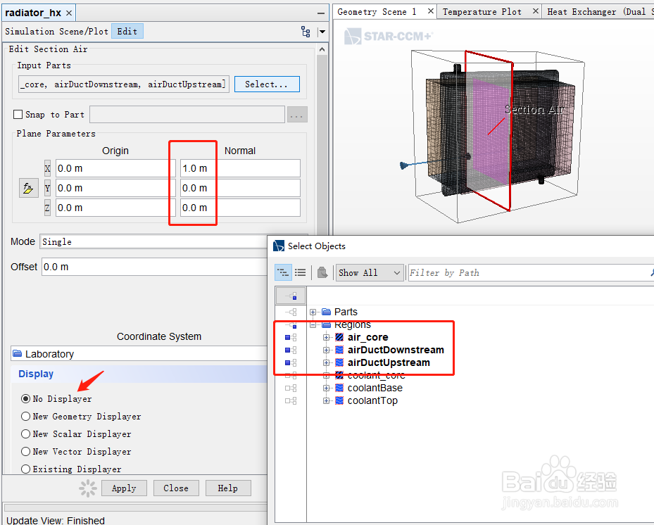
截面1:点击Derived Parts > New Part > Section > Plane,Input Parts选择[air_core,airDuctDownstream,airDuctUpstream],Normal向量为[1, 0, 0],勾选No Displayer,点击Create,将Plane Section重命名为Section Air。
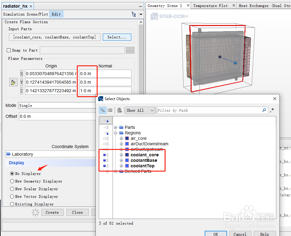
截面2:Input Parts选择[coolant_core,coolantBase,coolantTop],Normal向量为[0, 0, 1],勾选No Displayer,点击Create,将Plane Section重命名为Section Coolant。
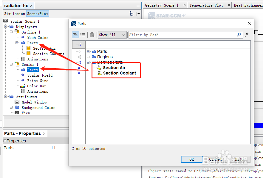
6、创建Scalar Scene监控温度。点击Scenes > Scalar Scene 1 > Displayers > Outline 1 > Parts,选择Section Air,Section Coolant。同理,Scalar 1 > Parts也选择这两项。Scalar Field > Function设为Temperature;Contour Style选择Smooth Filled;Color Bar,将Title Height设为0.04,Label Height设为0.035。
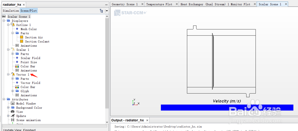
7、右键Scalar Scene 1 > Displayers,新建Vector监控冷却液的流速。Parts选择Section Coolant。
1、点击Stopping Criteria > Maximum Steps,设为1000。
2、保存,初始化,提交计算。
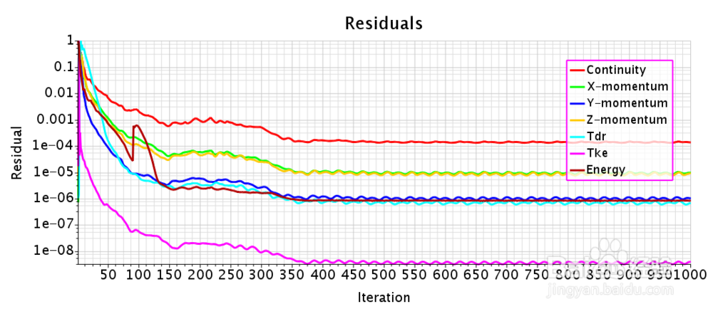
1、残差曲线。
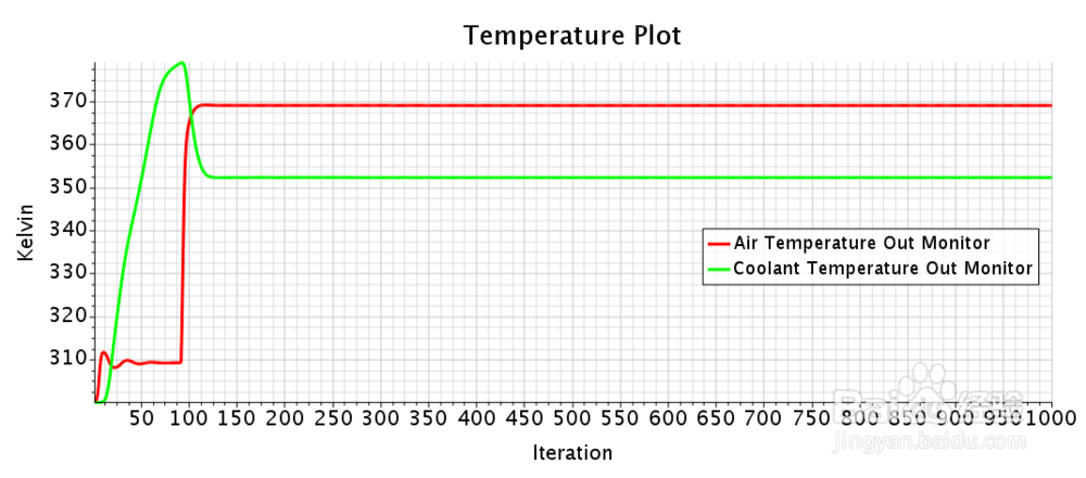
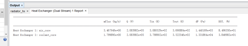
2、出口温度曲线。空气和冷却液的出口温度在迭代200步以后即达到稳定,空气由308 K上升到369 K,冷却液温度由380 K下降到352 K。
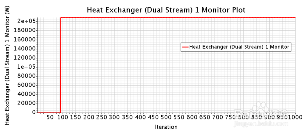
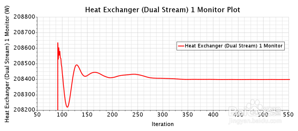
3、Heat Exchanger曲线。调整坐标轴尺度后可以看到,热交换量在迭代350步以后达到稳定,热交换量值208398.2 W。
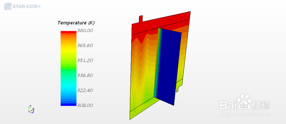
4、温度场云图。
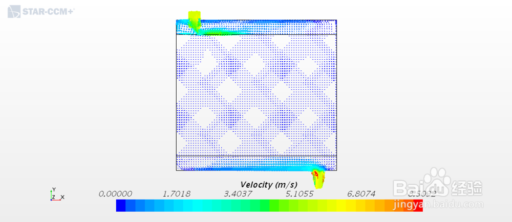
5、冷却液流速场。